Efergy Engage Resurrection

The Efergy Engage Hub#
Yonks ago, I got a whole-house electricicy monitor for cheap thanks to my workplace. The data was recorded and accessible via a website, (https://engage.efergy.com/dashboard). It even had a nice and simple REST API. The idea of getting the data on the internet instead of a dumb LCD screen was exciting at the time.
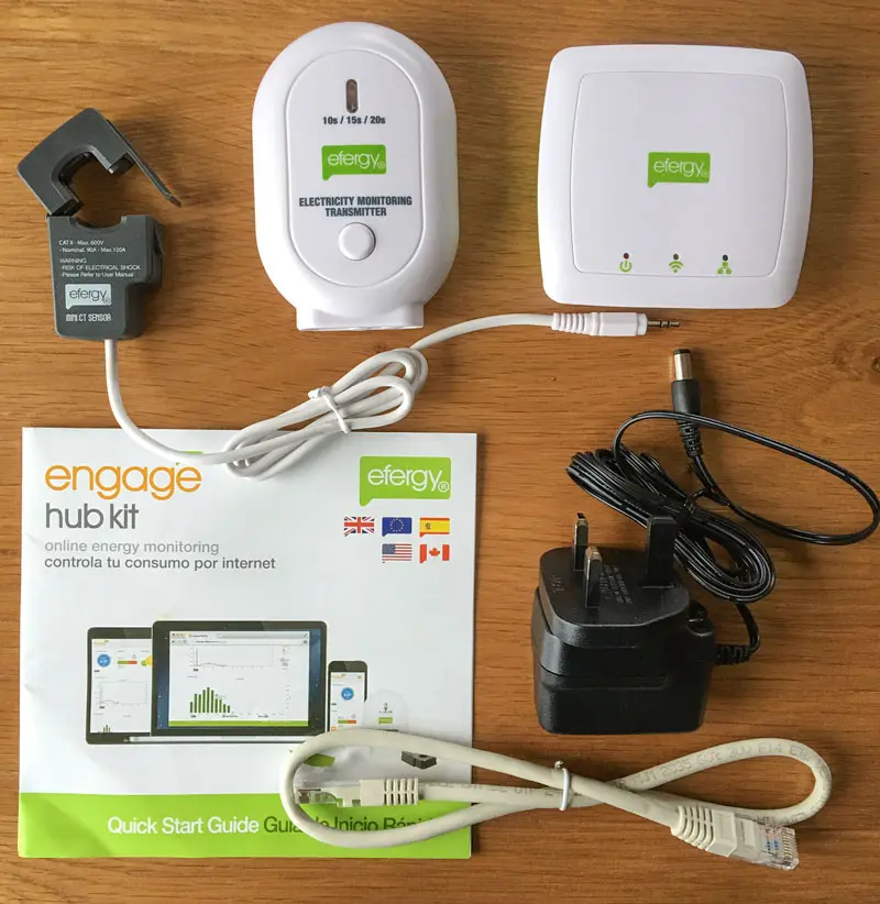
Here’s a contemporaneous review for context. The kit has two main parts; a 433MHz transmitter with a clamp ammeter, and a receiver with an ethernet jack to connect to the internet.
The clamp ammeter goes to the transmitter box that contains a microcontroller that simply takes readings and transmits them over 433MHz every 6 seconds. The 'receiver hub' in the top right has a 433Mhz receiver radio, and an ethernet plug. It’s hardcoded to send data to engage.efergy.com with HTTP requests.
Fast forward to 2026, and the efergy online platform has been shut off 🥀
How do I keep using the meter and keep the whole thing from becoming e-waste?
False Starts#
Fake Efergy Server#
Recreating an efergy server is an obvious solution that has been done, but it’s surprisingly difficult to run in 2026, since the hub can only make connections with SSLv3, which has been removed from modern software for being so old/insecure. I’m guessing this is the main reason for the cloud service shutdown.
Hacking the Receiver Hub#
I considered flashing the hub, either to try and patch the existing firmware to just use plain HTTP, or even with my own firmware that replicates the functionality. It’s using a PIC18F66J65 microchip, made by a company confusing called Microchip 🧐. These chips actually have a feature to perform in-circuit programming/debugging (ICSP). The hub even has what looks like the ICSP header on the board. Software called pickle can program the chip via the GPIO pins on a rasberry pi. I didn’t go down this path since it seemed pretty high effort. If you only have a raspberry pi and a lot of free time, go for it!
Software Defined Radio#
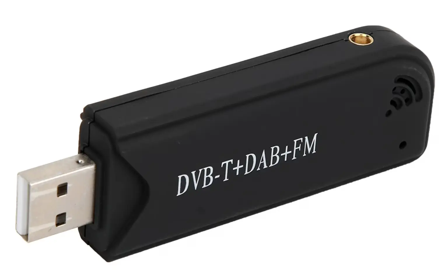
I had one of those RTL2838/rtl-sdr USB TV tuners sitting in a draw for years, can I use it to listen for the sensor’s transmissions? Nathaniel Elijah reverse engineered the wireless data sent by the sensor on 433MHz soon after the efergy was released. There are a few copies of his code with improvements floating on the internet, but a fairly recent and maintained version can be found in rtl_433.
OmniOS the pain#
Since I’m not normal, I installed it on my OmniOS NAS in a zone, since it’s running 24/7 anyway. I’m writing these tips for prosterity. rtl_433 is avaliable on most linux repos, so Skip below if you’re running a normal OS.
Compiling#
Compiling rtl_433 requires:
-
libusb
-
openssl (1.1 or 3)
-
librtlsdr
openssl is no problem, while libusb and librtlsdr can be grabbed from pkgsrc’s rtl-sdr package. cmake didn’t look in /opt for libraries, so I had to tell it where to look with some CLI arguments. It also needed POSIX_C sources included, so that it knew about constants like M_PI_2, NI_MAXSERV and TIOCGWINSZ. Finally, it needs to have lsocket and lnsl specified to the linker since functions for sockets aren’t in libc. The complete commands to configure and compile are grotesque:
cmake -DLibRTLSDR_INCLUDE_DIR=/zones/sdrzone/root/opt/local/include -DLibRTLSDR_LIBRARY=/zones/sdrzone/root/opt/local/lib/librtlsdr.a -DLibUSB_INCLUDE_DIR=/zones/sdrzone/root/opt/local/include/libusb-1.0 -DLibUSB_LIBRARY=/zones/sdrzone/root/opt/local/lib/libusb-1.0.a -DCMAKE_C_FLAGS="-D_XOPEN_SOURCE=700 -D__EXTENSIONS__ -D_POSIX_C_SOURCE=200809L" -DCMAKE_EXE_LINKER_FLAGS="-lsocket -lnsl" -B build
cmake --build build -j 10
Passing a USB device to a zone#
Since it’s talking to the sdr over USB, it needs access to the device. zonecfg lets you specify device resources, and even supports * to more neatly add multiple at once:
add device
set match="/dev/usb/bda.2838/0/*"
end
In theory that should be sufficent, with bda the vendor ID (Realtek), and 2838 the device ID (RTL2838 DVB-T). The above will allow access to all of the USB device file endpoints for the first RTL2838 connected (hence the 0).
Except rtl_sdr tries to be clever and automatically work out what USB device is an SDR. So it’ll crash unless it can enumerate all of the USB devices via the following files and devices:
/devices/pseudo/devinfo@0:devinfo
/etc/dev/.devlink_db
/dev/usb/hub1
/dev/usb/hub0
/dev/timerfd
I ran the program with truss to see what it tried to access that caused a crash then added it to the zone’s config:
add fs
set dir="/devices/pseudo"
set special="/devices/pseudo/"
set type="lofs"
end
add fs
set dir="/etc/dev"
set special="/etc/dev"
set type="lofs"
end
add device
set match="/dev/usb/bda.2838/0/*"
end
add device
set match="/devices/pseudo/devinfo@0:devinfo"
end
add device
set match="/etc/dev/.devlink_db"
end
add device
set match="/dev/usb/hub1"
end
add device
set match="/dev/timerfd"
end
add device
set match="/dev/usb/hub0"
end
Whats the practical difference between device and a lofs in this instance? No idea, maybe block or character devices work in one but not the other? I found very little info about doing this on the internet, making me feel like the only person on the planet trying to pass hardware devices to an Illumos zone. Honestly, you might be best off just running it in the global zone.
rtl_433#
Once it’s up and running, listening for the efergy sensor’s data is simple as specifying protocol 36 (Efergy e2 classic) and what frequency (433550000 Hz).
It has a bunch of options for the output, including text/csv log file, syslog, mqtt, or an influx database. I chose the http option that spins up a webserver makes it simple to glance in a browser.
rtl_433 -R 36 -f 433550000 -F http:0.0.0.0:80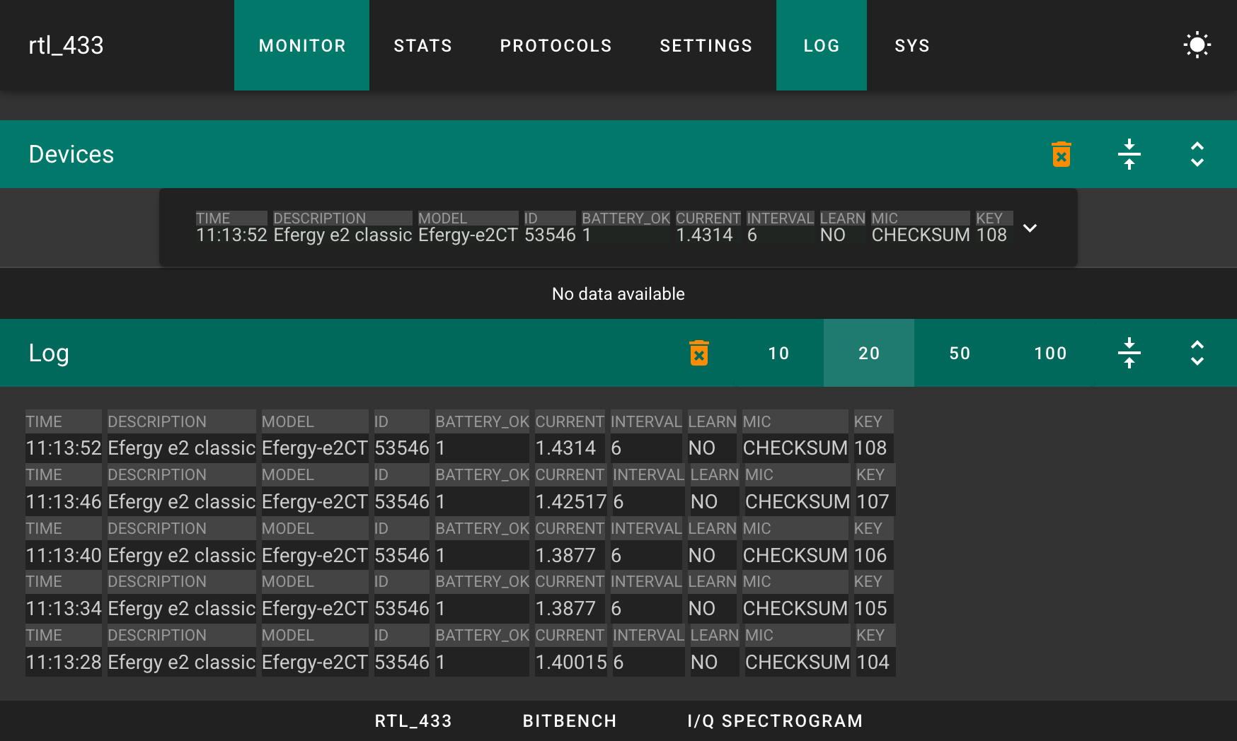
You can even just connect to port 80 and get JSON formatted updates as they arrive in what’s supposed to be a websocket:
nc -v 192.168.1.223 80
Connection to 192.168.1.223 port 80 [tcp/http] succeeded!
AD
{"time":"2026-05-04 13:52:18","description":"Efergy e2 classic","model":"Efergy-e2CT","id":53546,"battery_ok":1,"current":1.41895,"interval":6,"learn":"NO","mic":"CHECKSUM"}
2

AD
{"time":"2026-05-04 13:52:24","description":"Efergy e2 classic","model":"Efergy-e2CT","id":53546,"battery_ok":1,"current":1.44391,"interval":6,"learn":"NO","mic":"CHECKSUM"}
2
Bonus Round: Wait What is Power?#
The clamp meter reads current in amps. What I’m interested in is actually the power in Watts. How do you calculate the power?

While the clamp meter spits out readings with milliamp accuracy, I’m stuck making some guesstimates;
-
I’m assuming the precise RMS voltage of the AC should be 230V, but I’m not measuring it so it’ll be a bit wrong.
-
I’m assuming the clamp is splitting out averaged total current, so I can’t split out the active and reactive power components. I’m going to assume that everything in my house has a power factor of 1, when it’s probably less.
So we return to simply doing 230 times the current reading to give power in Watts…
Comment
- Username, 2026-01-27