Pimping my bPod Badge

The badge for bsides Canberra 2023 was an ode to the iPod nano. Snaps for Peter Rankin not just designing an awesome badge but for giving a stellar talk for it. I really appreciated the desire for the badge to be useful after the con for other projects and hacking. I’ve previously repurposed the 2018 badge to make my IR Blaster, so I can get behind the idea.
The 2023 badge is a neat package of screen, touch scroll wheel, USB-C and an ESP32-S2. This thing begs to be portable and held, but to save money didn’t come with a battery. Let’s fix it up.
Adding a battery#
Rifling the parts drawer, the smallest and easiest to use battery was a 750mAh lipo originally meant for use with micro drones.
File Photo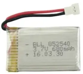
- Lithium ion charge controller.
- Battery over/under voltage protection. (Many batteries have this built in, my drone battery doesn’t 😥)
Lucky for me, the TP4057 exists on tiny modules on aliexpress. Looking at the TP4057’s datasheet now, it doesn’t mention voltage protection… I guess below 3.3V the bPod’s regulator will give up and that can limit the damage. 🤷
The lil charge module has separate input and output pins so that it can control charging and (supposedly) switch off the output when the battery gets too flat. This means we need the USB 5V separated from the battery VIN pad.
Removing this diode breaks the USB power circuit and gives us a pad to grab the 5V USB input from.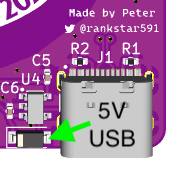
I’m sorry this is worse than an instructables diagram. It’s better than seeing my soldering.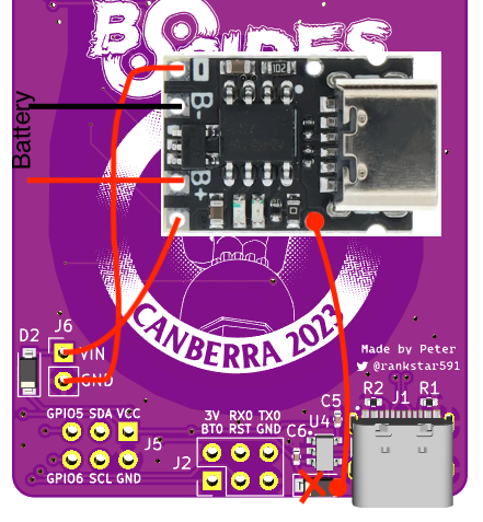
Don’t forget to wrap the module in heatshrink/tape so it doesn’t short anything on the back of the board.
Making a case#
Having a battery dangling off the back isn’t ideal. The badge was supplied with a rubber band to facilitate mounting batteries, an elegant solution, but I think I can do better.
I’ve only recently gotten a 3D printer and only printed existing models. Now I’ll need to design a case from scratch. Modern CAD software is thankfully free for hobbyists now, but it’s also gigantic and hard to learn the thousands of features. I discovered OpenSCAD, that lets you model via code/scripting rather than toolbars, menus and keyboard shortcuts. There’s an excellent tutorial that gets you going quickly. Even as a n00b not using modules and variables well, it was very nice to easily go back and change a measurement from an earlier step without lots of undos.
In terms of design, I really have no idea what I’m doing and just made the first thing I thought of. I like the profile of the board, so I sandwiched it with a back and front cover. The two top lanyard holes were dying to be screw holes, I measured for some spare screws I had laying around. I was hoping to cover the touchwheel with an embossed circle but it doesn’t seem to work through PLA+. So instead a big hole was required.
The back is full of little components that you don’t want to squish, many very close to the edge, making my sandwich design difficult. Luckily the kiCAD project files are available so I could check my calliper measurements with the original board layout.
I can’t believe there’s no HTML5 3D model viewer yet.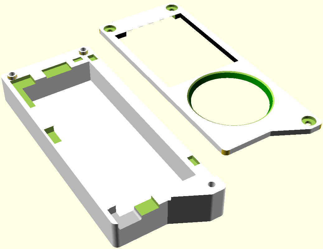
Here’s the SCAD file if you’re interested. It’s my first ever 3D model/scad file, I apologise for it’s poor quality.
The software#
Peter graciously provided the complete source for the bPod. As expected, it’s fucking excellent, and would be a great base to build off for projects. It is doing a LOT, with ‘apps’ separated out to easily build multiple functions. For simple single file Arduino projects here’s what’s needed to get the hardware going:
#include <Adafruit_GFX.h>    // Core graphics library
#include <Adafruit_ST7735.h> // Hardware-specific library for ST7735
#include <SPI.h>
// Take the TouchWheel.h and TouchWheel.cpp from firmware/touch/TouchWheel,
// chuck them in your project
#include "TouchWheel.h"

#define CS_PIN  34 // IO34
#define DC_PIN  33 // IO33
#define RST_PIN 38 // IO38
#define BKL_PIN 45 // IO45

#define TOUCH_000DEG  1 // TOUCH1 IO1
#define TOUCH_120DEG  2 // TOUCH2 IO2
#define TOUCH_240DEG  3 // TOUCH3 IO3
#define TOUCH_OK      4 // TOUCH4 IO4

Adafruit_ST7735 tft(&SPI, CS_PIN, DC_PIN, RST_PIN);
TouchWheel wheel(TOUCH_000DEG, TOUCH_120DEG, TOUCH_240DEG, TOUCH_OK, false);

void setup() {
	//Display setup
	pinMode(BKL_PIN, OUTPUT);
	pinMode(CS_PIN, OUTPUT);
	pinMode(DC_PIN, OUTPUT);
	pinMode(RST_PIN, OUTPUT);
	//INITR_BLACKTAB was in original firmware, GREENTAB works better on my screen.
	tft.initR(INITR_GREENTAB);
	tft.setRotation(2);
	tft.fillScreen(ST77XX_WHITE);
	digitalWrite(BKL_PIN, HIGH);
	//Alternatively control brightness with analogWrite(BKL_PIN, brightness);
	tft.setTextColor(ST77XX_BLACK);
	tft.println("Sup");

	// back LEDs control, turning all off for now.
	pinMode(10, OUTPUT);
	digitalWrite(10, LOW);
	pinMode(16, OUTPUT);
	digitalWrite(16, LOW);
	pinMode(21, OUTPUT);
	digitalWrite(21, LOW);

	//Touchwheel init
	wheel.begin();

void loop() {
	// Wheel logic
	int16_t clicks = 0;
	wheel.read();
	clicks = wheel.wheel_pop_clicks();
	while ( clicks > 0 )
	{
		//SCROLL_CLOCKWISE
		//Do something when touched
		tft.println("SCROLL_CLOCKWISE");
		clicks -= 1;
	}
	while ( clicks < 0 )
	{
		//SCROLL_ANTICLOCKWISE
		//Do something when touched
		tft.println("SCROLL_ANTICLOCKWISE");
		clicks += 1;
	}
	clicks = wheel.ok_pop_clicks();
	while ( clicks > 0 )
	{
		//KEY_OK
		//Do something when touched
		tft.println("KEY_OK");
		clicks -= 1;
	}
	clicks = wheel.forward_pop_clicks();
	while ( clicks > 0 )
	{
		//KEY_FORWARD
		//Do something when touched
		tft.println("KEY_FORWARD");
		clicks -= 1;
	}
	clicks = wheel.menu_pop_clicks();
	while ( clicks > 0 )
	{
		//KEY_MENU
		//Do something when touched
		tft.println("KEY_MENU");
		clicks -= 1;
	}
	clicks = wheel.back_pop_clicks();
	while ( clicks > 0 )
	{
		//KEY_BACK
		//Do something when touched
		tft.println("KEY_BACK");
		clicks -= 1;
	}
	clicks = wheel.play_pop_clicks();
	while ( clicks > 0 )
	{
		//KEY_PLAY
		//Do something when touched
		tft.println("KEY_PLAY");
		clicks -= 1;
	}
}
You can use Adafruit’s ST7735 Library to drive the screen. Search ‘adafruit ST7735’ in Arduino’s Library manager. You also still need the TouchWheel code imported for the original firmware. I have no idea how it works, going to assume magik.
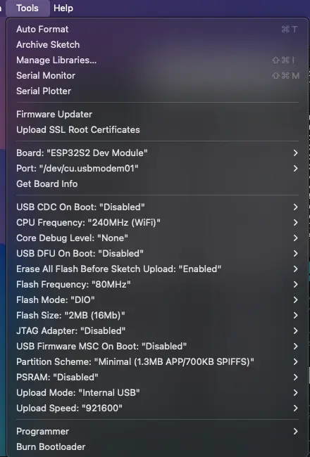
To set up the Arduino IDE, add the following to “Additional board manager URLs” in settings"
https://raw.githubusercontent.com/espressif/arduino-esp32/gh-pages/package_esp32_index.json
To program you’ll need to press both buttons on the back of the board at the same time, then the serial device will appear. The other key option is Flash Size: “2MB (16Mb)”. Unless you were lucky and got a bigger one.
What do#
So I have a confession to make, I’m not actually sure what to do with this thing now it’s made. As a test run, I decided to make it talk to my existing badge TV IR Blaster. So it can operate as a very weird TV remote when my phone isn’t within reach.
Hey at least it’s not conscious to experience it’s own lack of meaning.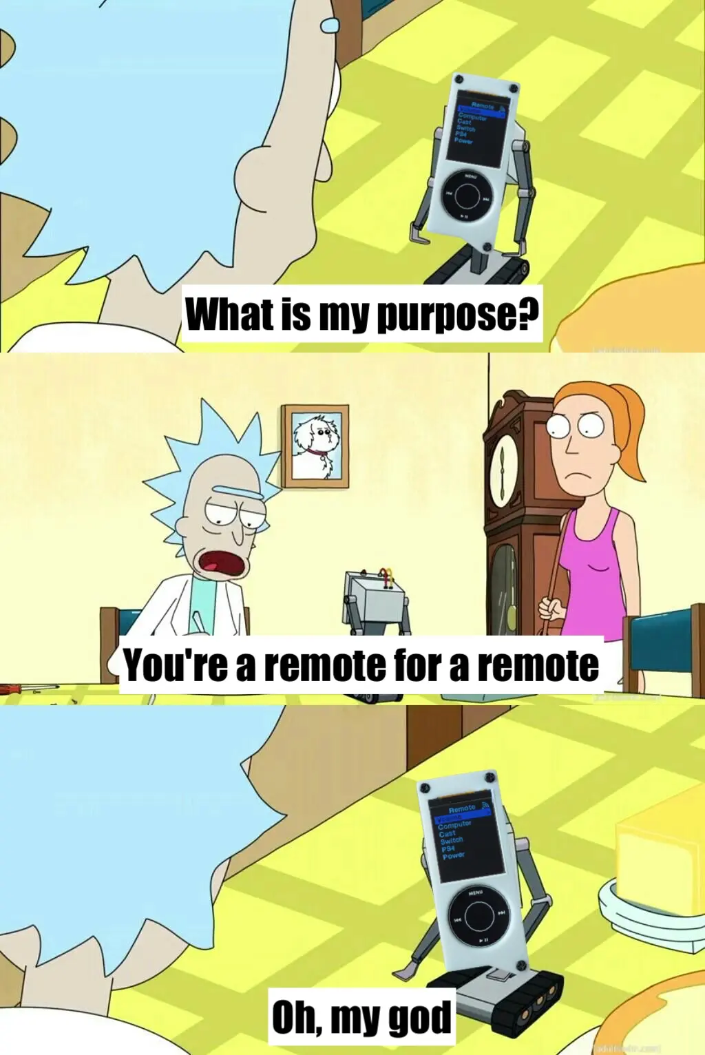
This required setting up a websocket client (not a popular thing to do!), entering deep sleep when not in use, and saving preferences for brightness to persist between sleeps. I was honestly surprised how quick and easy most of these were to implement, thanks to the amazing Arduino libraries available for the ESP32. Might go into more detail when I have a more interesting / mainstream appeal use case.
Next Steps#
- Use a flatter phone battery to reduce the thickness.
- Add a piezoelectric buzzer to give faint clicks when using the touch wheel.
- Figure out how to have the chip be reprogrammable without needing to take apart and press the buttons.
- Have actually useful features.
Comment
- Username, 2026-01-27