Controlling PC PWM fans with Arduino
I’ve got a whole bunch of fancy Noctua PWM fans in my PC I want to control the speed of. How do I boss them around? The most authoritative source of how these fans communicate is from an Intel specification. Even better is a whitepaper by Noctua themselves that describes every detail you could ever want to know.
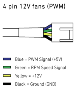
Cos numbering pins is for suckas
Okay so at least we aren’t going to be reverse engineering these fans. What exactly do they want on that PWM input pin?
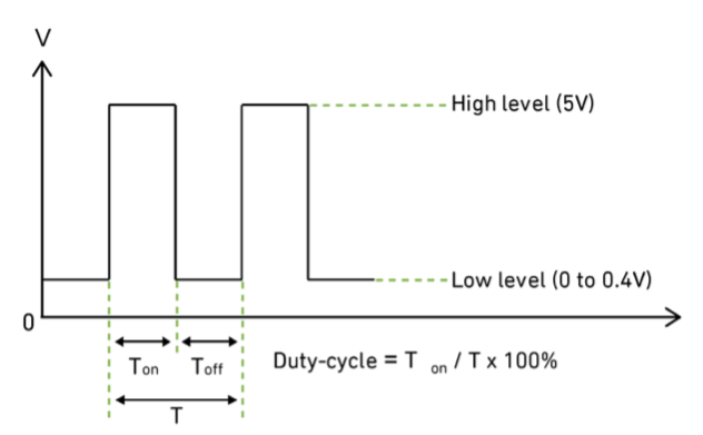
- Target frequency: 25kHz, acceptable range 21kHz to 28kHz
- Maximum voltage for logic low: VIL=0,8V
- Absolute maximum current sourced: Imax=5mA (short circuit current)
- Absolute maximum voltage level: VMax=5,25V (open circuit voltage)
- Allowed duty-cycle range 0% to 100%
A 5V PWM signal? Finally something made for our Arduino 5V logic world! We’ve got 6 PWM outputs. I’ve never bothered to check a PWM’s frequency, but that acceptable range looks wide AF so it’ll probably be fine. Let’s see what is the Arduino spitting out:
490 Hz (pins 5 and 6: 980 Hz)
- Arduino analogWrite() Reference
Oh dear. As loose as these fans are, I fear being that wrong won’t work. Sadly the standard functions don’t let you change this, we need to go deeper…
Turns out the ATmega328P can change this frequency, since the only frequency it knows is the 16 MHz clock crystal on the board. All other frequencies are just that divided up. There are actually three separate timers that can operate at different frequencies;
- Timer0 on pins 5 & 6 (8 bit)
- Timer1 on pins 9 & 10 (16 bit)
- Timer2 on pins 3 & 11 (8 bit)
Timer0 is also responsible for time keeping functions like millis() and delay(), so changing it’s frequency will mess them up. Let’s avoid that if we can.
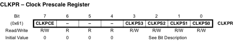
The frequencies these run at are controlled by registers in the ATmega328P. Don’t fear registers, they are just special bytes of memory that represent specific settings for the chip instead of numbers or characters. When you’re working on something with 2.5k of RAM, storing settings in a human readable json file is out of the question. Instead you cram it into a single byte, like a TCP header flags for you normies upstack.
But then how do you know what bits do what? You pray that the chip has decent documentation and that the values required make some kind of sense. Normally a library will configure these for you, hence functions like pinMode().
In this case, there are dozens of settings/registers that control the outputted PWM waveform, which have to be calculated with the arduino’s 16 MHz clock. It’s a pain in the arse, and clear why there isn’t an official function to specify a frequency. But this is why we are using an arduino, somewhere someone has surely already figured it all out. This lad has done the valiant work to give you exactly 25KHz output on 4 pins, but it ends up making all time functions run at half speed and messes up pins 6 & 11, along with changing how pins are set a bit.
I also found a wonderful page describing what can be set for individual timers without messing with the rest of arduino’s setup. The closest is 31.3kHz. Which is still wildly wrong, but I thought worth a shot. Luckily all of my Noctua fans responded to this signal, though I can’t promise other fans will.
// set timer 1 divisor to 1 for PWM frequency of 31372.55 Hz
TCCR1B = TCCR1B & B11111000 | B00000001;
So with a single line added to our setup() we’ve got pins 9 & 10 able to control our fans. Hook up the 12V and ground, and you’re good to go. For my setup this is fine, as I only have two groups of identical fans that I’d like to control, but timer2 is there for the taking if you’d like more.
Also ignored is the tachometer pin, which sends two pulses per revolution. You’d probably want to use interrupts to count them, but the uno only has two pins for that. I’m pretty happy with a % being sent to represent fan speed instead of accurately measuring the real rpm, so I’m just gonna not worry about it.
Comment
- Username, 2026-01-27