Aoostar WTR pro Hardware Monitoring on OmniOS

As you know, I love monitoring my computers, and jank DIY fan controllers. I performed a mod on my Aoostar WTR Pro, replacing the stock 120mm, 1200rpm fan[1] with a 140mm 2000rpm one I had laying around[2]. This meant the new fan was blowing faster and louder than it probably needed to. There are settings in the BIOS to adjust the fan speed, but they are pretty hard to know what speed it’ll actually end up at, and how loud/hot that will be.
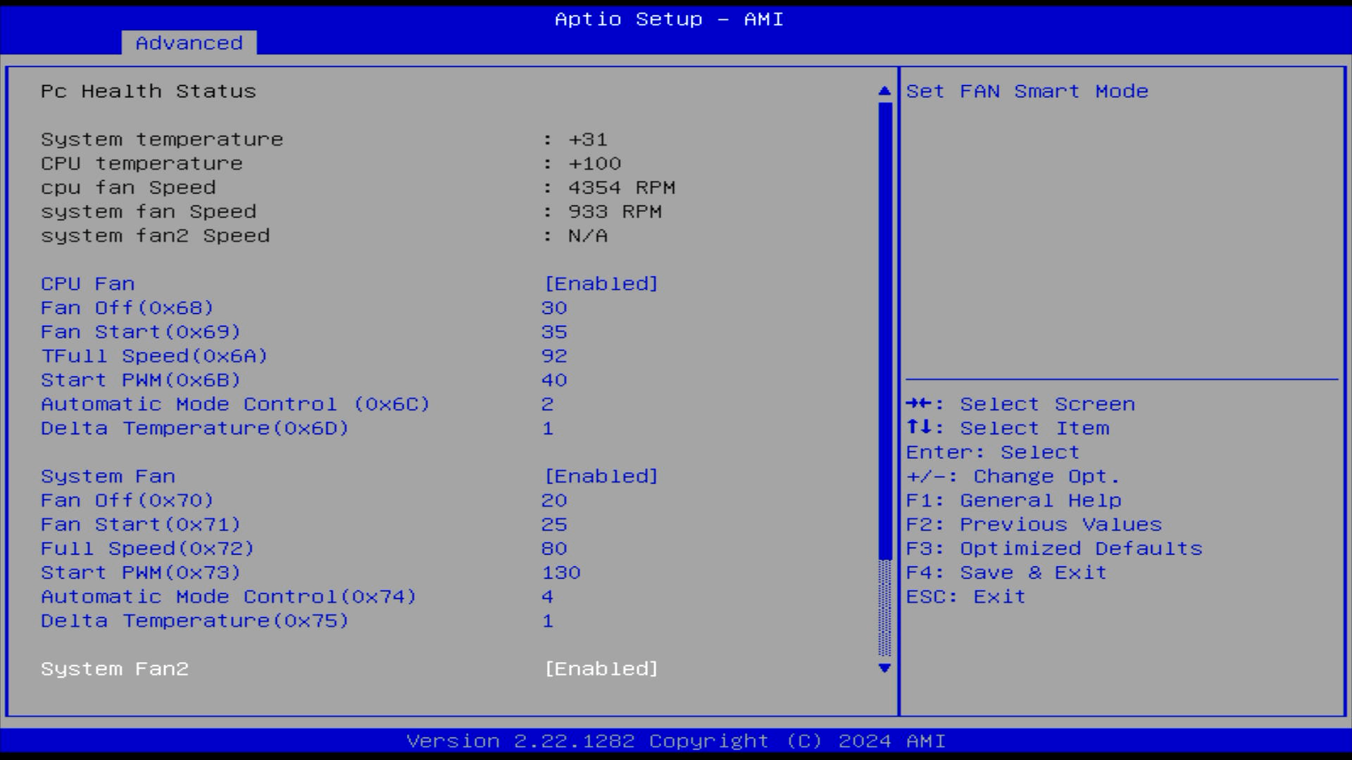
Ah yes, Automatic Mode Control two…
Setting the fan speed from the OS would be great. I could even base it on the actual HDD temperatures collected via SMART, instead of the 'system temperature' which is taped to the outside of the plastic HDD cage. I was really inspired after reading a blog on notebookcheck. Poor Christian goes through the pain we’ve all felt, trying random programs, with none of them working. The problem is that 'API that controls fans' isn’t really a thing, there are loads of fan controllers out there, speaking their own undocumented protocol, and it’s a struggle to know where to begin and what things to search for.
The Hunt#
So I interrogated my PC, looking through ACPI Tables, SMBuses, I2C, PCI. In my desperation, I even asked Claude for help looking, to which it said a load of useless things, then this gem
Boot a Linux live USB temporarily just to identify what chip you have
I didn’t do that, but I did find an article on medium by Dmitrii Kulikov that did that exact thing for me. sensors-detect said that the board had a ITE IT8613E Super IO Sensors chip, and indeed he got it working with a driver for that series of chips.
This is a Super I/O chip, that talks over the Low Pin Count bus (LPC). Hey the LPC bus keeps showing up in my blog.
A kernel driver?!#
I thanked Claude for helping, and was about to get to work researching and working out how to talk to this chip, when it offered to write a driver for me.
Now listen, I’m usually writing scripts in python, so a kernel driver feels way to close to 'real programming' for me to even approach. Then again, they are often just a single C file. Might this be the kind of small, limited scope project that LLMs can actually do?
Then again again, we are talking about running AI code inside the kernel. A crash here will bring down the entire computer, I’d need to walk over and physically reboot it.
So the first proof of concept driver it spat out, I carefully went through to personally validate that it at least won’t immediately crash. Though honestly, by the third iteration, I was blindly copy pasting that stuff and slamming run.
ITE IT8613E#
Lucky for me, the it87 linux driver not only contains a working example, but also a collection of all known documentation for the series of chips:
Please ignore the ‘confidential’ watermark.
Being a LPC device, it basically talked ISA from a software point of view. Being so ancient, it’s pretty easy to communicate with, with Illumos having functions to read and write to the memory addresses that correspond to the device.
Knowing what registers and what their contents represent is frankly the tricky part. Even with the existing linux driver, it supports multiple chips so the ones needed specifically for the IT8613E isn’t immediately obvious. I gave Claude the it87.c file, hoping it could do that reading and understanding for me, but it never quite got it right. For the fans, it would try to read six fans (should be five) while offering PWM control for only 3 of them (Should also be five). It also did the RPM calculation incorrectly which I had to fix myself.
The temperatures it did okay with, seemingly matching the CPU temperature with the existing Illumos driver for the CPU.
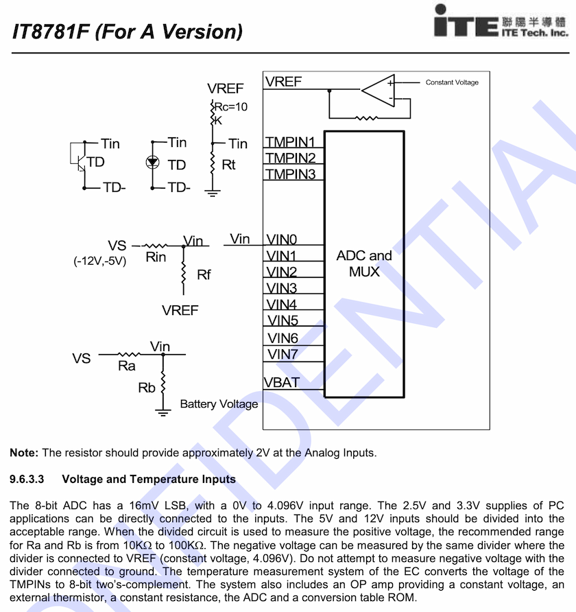
The voltage levels were a complete clusterfuck. As shown above, the ITE chips have generic analog to digital converters (ADCs) that can read the voltage on an input pin. They spit out an 8 bit value for each, from 0V up to their operating and/or reference voltage, anywhere from 2-4V. Each chip has a slightly different number of pins, and even a different increment. On most, each digital step represents 12mV, but some do 11mV, or even 10.9mV.
That’s just the chip differences! Each motherboard can hook up voltages in whatever order they want. Oh and if you want to measure voltages above 4V, the board needs to use a voltage divider. Say you’d like to measure a 5V line, you can put two identical resistors in series, so that the voltage in between is halved. That way the ITE chip can measure the 2.5V, halved value with it’s ADC, then in software you can multiply by 2 to get back to your true 5V line value. Most sane people arrange it to give a clean integer division, but there’s nothing stopping an OEM from chucking whatever values for the Ra and Rb resistors. So really you need to rearrange ohms law so that you reverse the voltage divider:
`Vs = "Vin" xx ("Ra"+"Rb") / "Rb"`
How are the voltages connected, and what values are the voltage dividing resistors? It’s seemingly different for each board design. To know for sure, you gotta either disassemble the OEM’s software, or reverse engineer the PCB. How does Claude tackle this? It bullshits. It simply made up labels for '5V, 12V, 3.3V, battery… etc' Then it made up multiplier values to make the readings match the label. I found it to be a microcosm of the whole 'AI' craze; Tell it to do something, and it indeed does do some of what you asked, but also bullshits the result to look correct. I spend an embarrassingly long time seeing voltages reported that seemed plausible, only to discover they were all nonsense when looking through the code.
The Iteration Cycle#
Claude got me going shockingly quickly, spitting out a bunch of files:
it87.c-
The driver code.
it87.conf-
The driver configuration file.
makefile-
Telling the compiler what to do.
It also told me how to install the driver[3]:
# compile
make

# Copy the driver into the folder for 64 bit x86 drivers
cp it87 /kernel/drv/amd64/

# Copy the driver config specifying the driver as a
# pseudo device so that it always loads.
cp it87.conf /kernel/drv/

# Tell the system about the driver
add_drv it87
Nothing crazy, but to be frank it would have taken me a while to figure out the exact headers to include, what gcc and ld flags are needed, and where to put the files. If you wanted to do this properly, I’d highly suggest the book 'Writing Device Drivers' available on the Illumos website. Details for compiling and loading drivers are all the way in Chapter 21.
Since I wanted to be careful, I simply copy/pasted new versions of it87.c and manually compiled and installed. Pretty quickly I included the install steps in the makefile. Early versions simply had compile errors, then it used dmesg to print debug lines to quickly get output.
dmesg | tail -n 20
...
it87: [ID 131541 kern.notice] NOTICE: it87_fan: Loading module (pseudo-device version)...
it87: [ID 931803 kern.notice] NOTICE: it87_fan: Pseudo-device attached
it87: [ID 353662 kern.notice] NOTICE: it87_fan: Attempting to detect IT8613E...
it87: [ID 981873 kern.notice] NOTICE: it87_fan: Chip ID = 0x8613
it87: [ID 100015 kern.notice] NOTICE: it87_fan: IT8613E detected!
it87: [ID 460543 kern.notice] NOTICE: it87_fan: HWM base address = 0x0a30
it87: [ID 480160 kern.notice] NOTICE: it87_fan: Fan 1 = 0 RPM
it87: [ID 104467 kern.notice] NOTICE: it87_fan: Fan 2 = 0 RPM
The appearance of progress was really quite exciting. Then I ran out of free credits and had to wait 5 hours to put the finishing touches. AKA, have it actually spit out something other than 0 RPM…
Surfacing to userspace#
To get the readings accessible to normal programs, I wanted to use the fairly recent ksensor feature in Illumos. Shout out to Robert Mustacchi who has blogged about their contributions to ksensor and general hardware monitoring on Illumos. The driver tells the kernel about sensors, and it’ll populate /dev/sensors for you. I thought tmtopo would simply read whatever was in there, but unfortunately not, so I Claude had to write a program that reads the sensors too. Also it doesn’t specify fan speed or know about rpm values, so I had to do that with a generic ioctl device, also requiring a specific program.
# fanctl list
Fan Status:
  Fan 1:  1394 RPM
  Fan 2:   699 RPM

PWM Status:
  PWM 1:  40/255 ( 15%) - Automatic
  PWM 2:  84/255 ( 32%) - Manual
I still left in the voltages' raw readings, maybe one day I’ll figure them out…
# sensorreader /dev/sensors/*/*/*
/dev/sensors/temperature/cpu/procnode.0: 302 (kind=4, unit=6)
/dev/sensors/temperature/motherboard/cpu: 37°C (unit: Celsius)
/dev/sensors/temperature/motherboard/HDDcage: 32°C (unit: Celsius)
/dev/sensors/voltage/motherboard/in0: 0.649V (649000 µV)
/dev/sensors/voltage/motherboard/in1: 1.232V (1232000 µV)
/dev/sensors/voltage/motherboard/in2: 1.716V (1716000 µV)
/dev/sensors/voltage/motherboard/in3: 1.474V (1474000 µV)
/dev/sensors/voltage/motherboard/in4: 1.606V (1606000 µV)
/dev/sensors/voltage/motherboard/in5: 1.485V (1485000 µV)
/dev/sensors/voltage/motherboard/in6: 2.695V (2695000 µV)
/dev/sensors/voltage/motherboard/in7: 0.341V (341000 µV)
/dev/sensors/voltage/motherboard/in8: 1.584V (1584000 µV)
/dev/sensors/voltage/motherboard/in9: 0.000V (0 µV)
The outputs are pretty barebones but enough for me to wrap in my own scripts that monitor temperatures then control fan speeds. Claude spent a while not wanting to write the sensorreader program, claiming I should use the fictitious sensorstat:
Claude: Actually, wait - can you try sensorstat instead? The ksensor framework has a dedicated sensorstat command that should show all ksensor-registered sensors.
Me: Where did you get the
sensorstatcommand from? It’s not in OmniOS or it’s packages, searching online didn’t return anything, searching the illumos codebase also didn’t find anything by that name.Claude: Ah, you’re absolutely right - I was confusing OmniOS tools with what I thought existed. There’s no sensorstat command.
Me: 🙃
Classic Claude! Once it believed me, it created sensorreader.c in one go and appears to work fine enough.
Check out all the code on Github if your interested. Despite my success I remain deeply suspicious. I pointed out all the things it got wrong with the IT8613E, because I’m familiar with hardware and microcontrollers. It probably fucked up a lot on the Illumos driver side of things too, I’m just too ignorant to recognise it.
Comment
- Username, 2026-01-27